Course overview
One of the standout courses in the engineering physics degree at UBC is ENPH 253. Technically called “Instrument Design”, this class is more commonly referred to as “Robot Summer”. Teams of four students work for six weeks to create a fully autonomous robot, which can navigate a course. Then, they compete to see whose ‘bot is the best.

The theme for this year’s competition was “Pet Rescue”. We needed to design a robot which could navigate a course, detect stuffed animals, pick them up, and bring them back to a safe area. The full competition rules can be found here.
My teammates were Joshua Chung, Emma Duong, and Ellen Brisley. Joshua led chassis design, Ellen did claw design and sensing circuitry, Emma did circuit design and troubleshooting, and I did arm design and software. Our goal for this competition was to minimize risk – both during development, as well as during the competition. Because of this, we opted to design a robot that had as few moving parts as possible, speeding up development and giving more time for integration.
Strategy
Our strategy was to pick up the pets one at a time and drive them back to the start. This allowed us to forego a basket or a launcher, saving us space on our robot and development time. It also meant that our robot “locked in” its points frequently, whereas a team using a basket could lose all their progress if they tipped over near the end of their run. This allowed us to score a consistent number of points. This was important, because a robot needed to win multiple matches to win the competition.
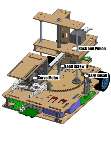
We selected a design with a three-axis arm using radial coordinates – a stepper motor drives a Lazy Susan for the theta axis, a geared DC motor runs the lead screw giving vertical motion, and a second stepper motor drives a rack and pinion for radial motion. This design allowed us to easily actuate the arm back and forth to pick up pets, unlike a more traditional robot arm, which required multiple motors to move at the same time to achieve horizontal motion.
To sense the pets, we used two mechanisms. For broad sensing, we used VL53L0X LiDAR time of flight sensors. We initially hoped to use ultrasonic distance sensors, as these are simpler, but they did not work well on the soft plushies. The LiDAR allowed us to detect when there was a pet nearby and told the drive system to stop.
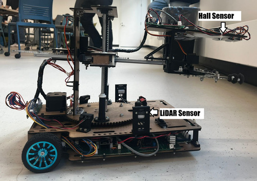
We also used a custom hall effect circuit board. This measured the magnetic field from small magnets placed on the pets and amplified the signal. The sensors were placed above the claw, so that we could sweep the arm with the claw retracted and extend the claw once the pet was detected – without having to reposition the arm in between steps. The combination of these two sensor systems allowed us to quickly and precisely pick up the objectives.
My Role
I designed both the vertical and rotational degrees of freedom for the arm. I used Onshape to create a CAD model for the arm. This model needed to incorporate both existing components (motors, lead screw, buttons), as well as custom fabricated elements.
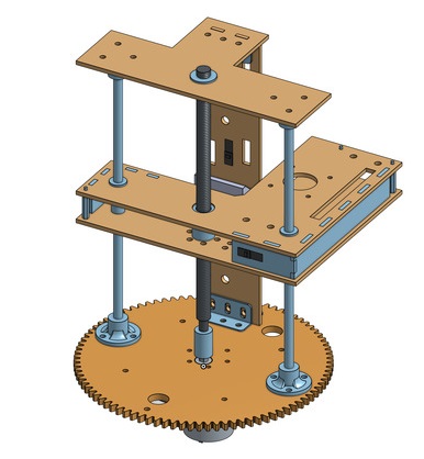
The platform which travelled along the lead screw was one of the most interesting elements to design. Initially, we planned to construct it out of a single sheet of 3mm hardboard. However, after testing, we determined that this was too flexible, leading to excess play in the arm. We added a second sheet of hardboard above, separated by four hardboard connectors. By adding a second sheet 2cm above, we increased the second moment of area by a factor of roughly 350, leading to a much more rigid platform. A second set of bushings on the additional platform further reduced play.
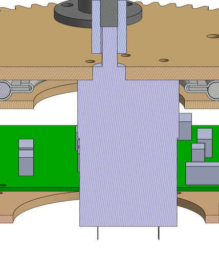
To reduce the number of parts required, and save vertical space on the robot, we opted to directly drive the lead screw from a geared 300 RPM motor. This required mounting the motor through the lazy susan, into the base of the chassis. This also meant that we were unable to encode the motor to determine the height of our claw. We determined there were only three heights the claw would need to be at during the competition. This meant that we could place a button at each height, using a cam mounted on the lead screw platform to press them.
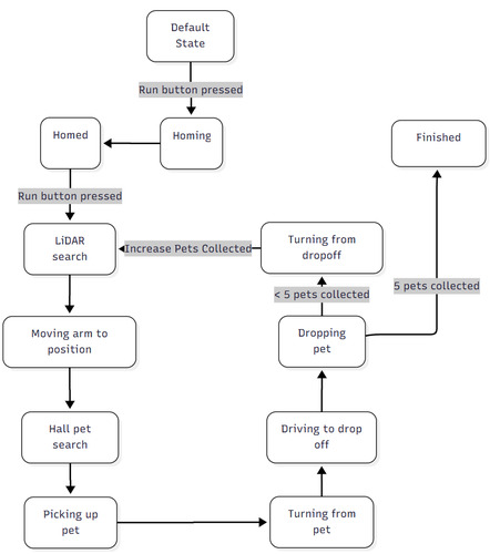
To keep our code simple, we opted to use a state machine to handle the robot, as it progresses through the course. When a dedicated button on the robot is pressed, it first homes, and then on a second click begins running. It then loops through the same 8 states, picking up one pet for each iteration. The behaviour in each state is dependant on the number of pets picked up. For example, for the first two pets, the robot will move its claw to the low height, while for the one on the pillar, it will instead go to the top height.
I wrote all of the software for the robot in the VSCode extension PlatformIO, using the C++ programming language. To structure the program, I followed an object-oriented approach. I found learnCPP to be an incredibly helpful resource for this. Although it took longer to initially program the objects, it made the final integration of all elements a lot easier.
I encountered two interesting challenges while writing the software for the robot. The first was that our H-bridge motor drivers were vulnerable to shoot-though, which is when both sets of gates are open, leading to a temporary short of the circuit. There was a slight hang time after we stopped supplying voltage to the gate of the MOSFET, before it truly shut off. to combat this, we had to add a slight, nonblocking delay whenever we changed motor direction. The second challenge was that the LiDAR sensors took 40 milliseconds to read from. Although this might seem like a short time, the PID control loop for the drive motors needed to be called every 5 milliseconds. To solve this, we used the second core on the ESP32, dedicating it to polling the LiDARs. Communication between the two cores was made safe using C++’s std::atomic.
Competition
Below, you can see a closeup video of our robot collecting the first three pets, recorded as we were still fine-tuning the software
Ultimately, our strategy was quite effective. We were able to consistently pick up 4-5 pets in each run. Most other teams were picking up anywhere from 1-4 pets per round. Below, you can see a video of our first run during the competition.
Unfortunately, although we had tested the robot extensively before the competition, things always have a way of going wrong at the worst time. During the second round, a JST connector for the lead screw position sensor failed, which caused the lead screw to over-rotate, slamming our claw into the top of the robot. Although we attempted to troubleshoot between rounds, we could not repair the issue in time, meaning we had to forfeit.